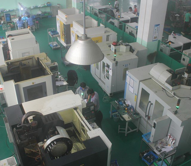
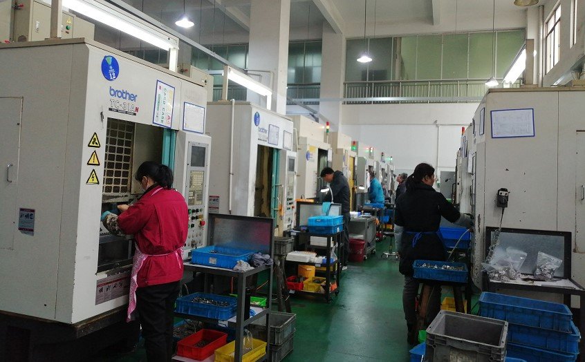
Workpiece accuracy is extremely paramount in the CNC Machining industry. In some cases, even the tiniest error can be unimaginably devastating. The scale-up to which the required geometric parameters of the blank satisfy the ideal geometric parameters specified in the CAD design after processing is termed as machining accuracy. Processing accuracy will be as better as we shortened the difference between our CAD design and manufactured part.
While processing the workpiece, numerous factors affect the accuracy. As, few of the factors are such that cannot be controlled, so, it is impractical to obtain an ideally matched product with our CAD design. Therefore, there will be a few errors in the part processing. These are called machining errors.
So, to obtain an excellent dimensional accuracy of the workpiece during the CNC machining process, we discuss the following three important aspects.
- How to obtain the dimensional accuracy of the parts
- Methods of obtaining shape accuracy
- Methods of obtaining position accuracy

How to Obtain the Dimensional Accuracy of the Parts?
Let’s first discuss, how to obtain the dimensional accuracy of the parts? Here, we will discuss five important methods that will help in getting parts accuracy.
1: Trial Cutting Method
In the trial cutting method, we usually do two or three trials to get the required geometric specifications of the part. Start with cutting a small part of the machined surface. Just measure the size of the test cut. Then, make adjustments in the position of the cutting edge of the tool relative to the workpiece. This will be done following the processing requirements. When these all steps are completed, then just go for a cut and then measure. If after two or three trial cuts and measurements, good conformity in the required geometric specifications and CAD design is achieved, then cut the entire surface.
This trial cutting method works on the cutting-measurement-adjustment-retry loop. This loop will have to be repeated until we obtain the required dimensional accuracy of the part.
The merits of the trial cutting method are, high processing accuracy can be achieved and no completed and expensive devices are required. Its demerits include, it requires too much time to make multiple trial cuts, adjustments, measurements, and calculations. It offers low efficiency and demanding for an inexperienced worker. The quality that gets through this method is unstable. It is only recommended for single-piece small batch production.
2: Adjustment Method
In this method, a sample or standard part is used to get the exact relative positions of machine tools, fixtures, cutting tools, and workpieces. This results in better dimensional accuracy of the workpieces. The reason being, we accurately measure the dimensions before starting the process. So, there is no need of cutting again and again to make adjustments. In this way, the size of the workpiece is being set once and remains unvaried during the whole process. Determining the position of the tool using a tool block in a milling machine fixture is an example of this method.
The adjustment method is mainly used to make the tool reach a certain position accuracy relative to the machine tool or fixture and after that, a batch of workpieces can be processed. It is done using a fixed distance device or the tool setting device on the machine tool or the pre-set tool holder.
The machine tool feeds and then cuts in accordance to the dial, that is a kind of adjustment method too. This method prerequisites the use of the trial cutting method to determine the scale on the dial. For large productions, tool setting devices such as fixed-range stoppers, prototypes, and prototypes are often used for adjustment.
The adjustment method offers superior processing accuracy and stability than the trial cutting method. It has higher productivity. It is preferable and most suited for batch production and mass production.
3: Fixed Size Method
In the fixed-size method, the corresponding sizes of the tool are used to make certain the sizes of the processed parts. Standard-sized tools are used here and the size of the machined surface is determined by the tool size. This means a tool with a specific dimensional accuracy (like a reamer, a reamer, a drill, etc.) is used to make sure the workpiece’s accuracy (such as a hole).
The fixed size method offers easy operation, high productivity, and relatively stable processing accuracy. It does not require a seasoned worker to execute. It is used in many types of productions such as drilling, reaming, etc.
4: Active Measurement Method
In this process, the geometric parameters of the part are being measured during the machining process. Then, these measured dimensions are being compared with the dimensions mentioned in the CAD design. If both the dimensions match well then, the process remains to continue otherwise it is stopped.
In an inactive measurement method, the value can be shown digitally and to do so, we have to add a measurement device to the processing system. This method offers a stable quality and high productivity.
5: Automatic Control Method
This method offers automated part manufacturing. It consists of a measuring device, feeding device, and control system. It intelligently integrates the measuring device, feeding device, and control system. In this way, the machining process is successfully executed by the system.
To get the required part dimensions, a series of actions are being performed such as size measurement, tool compensation adjustment, cutting processing, machine stoppage, etc. These all the steps are executed automatically to obtain the required dimensional accuracy.
What is automatic measurement and digital control meant in the automatic control method and how these are executed? It is explained as follows in detail
Automatic measurement means that there will be a measurement device for automatic size measurement of the workpiece on the machine tool. Once, the workpiece matches the required size then the measuring device will issue an instruction. This instruction will tell the machine tool to stop working.
By digital control, it means that, on the machine tool, there will be servo motors, rolling screws, nut pairs, and a complete set of digital control devices. These devices will help to control the precise movement of the tool post or worktable. A pre-programmed program is used to evaluate the size.
The automatic control method offers a stable product quality, high productivity, good processing flexibility, and adaptability to multi-variety production.
Methods of Obtaining Shape Accuracy
There are three methods to obtain the shape accuracy of the part and discussed below
1: Trajectory Method
A method in which the trajectory of the tooltip movement is used to form the shape of the machined surface is termed as trajectory method. Ordinary turning, milling, planning, and grinding all belong to the tooltip trajectory method. The accuracy of the forming movement determines the shape accuracy.
2: Forming Method
In this method, the shape of the machined surface is obtained from the geometry of the forming tool. Which is used to replace certain forming movements of the machine tool. Informing method, the shape accuracy is mainly determined by the shape of the blade.
3: Generative Method
In this method, the shape of the machined surface is obtained by using the envelope surface formed by the tool and the workpiece. The gear hobbing, gear shaping, gear grinding, knurled spline, etc all belongs to the generative method. In the generative method, the shape accuracy is mainly determined by the shape accuracy and generative motion accuracy of the blade.

Methods of Obtaining Position Accuracy
In machining, the position accuracy of the machined surface is mainly obtained by the clamping of the workpiece
1: Directly Find the Correct Clamping
In this method, a dial indicator, marking plate, or visual inspection is used to efficiently find the position of the workpiece on the machine tool.
2: Draw the Line to Find the Correct Installation Clamp
In this method, the first step is to draw the centerline, symmetry line and the processing line of each surface to be processed on the blank. These lines are drawn according to the CAD design. After that, the workpiece is being installed on the machine tool, and the clamping position of the workpiece is being aligned on the machine tool according to the drawn lines.
This clamping method offers low productivity, low accuracy, and high technical requirements for workers. It is recommended to use for the processing of complex and bulky parts in small batch production. Or where the blank size tolerance is large and cannot be directly clamped by fixtures.
3: Clamping with Clamps
In this method, the fixture is specifically designed according to the process. The positioning elements on the fixture can easily settle the correct position of the workpiece relative to the machine tool and the tool. In this method, the positioning accuracy of the workpiece can be ensured without alignment and the clamping productivity with the fixture is high.
This method offers high accuracy, but it requires designing and manufacture special fixtures. These will be used in the batch and mass production.
If you get any jobs to quote, please feel free to email us at sales@imachinepart.com and my professional team will always get back within 24hours.

